Perkins1206-E70TTA柴油發(fā)動(dòng)機(jī)引擎控制組件ECM電腦控制模塊供應(yīng)商,Perkins1206-E70TTA柴油發(fā)動(dòng)機(jī)引擎控制組件ECM電腦控制模塊技術(shù)價(jià)格規(guī)格咨詢(xún)服務(wù),Perkins1206-E70TTA柴油發(fā)動(dòng)機(jī)引擎控制組件ECM電腦控制模塊零配件供應(yīng),Perkins1206-E70TTA柴油發(fā)動(dòng)機(jī)引擎控制組件ECM電腦控制模塊售后服務(wù)中心,Perkins1206-E70TTA柴油發(fā)動(dòng)機(jī)引擎控制組件ECM電腦控制模塊,Perkins1206-E70TTA柴油發(fā)動(dòng)機(jī)引擎控制組件ECM電腦控制模塊詳細(xì)的技術(shù)參數(shù),

首頁(yè)
產(chǎn)品展示>Perkins1206-E70TTA柴油發(fā)動(dòng)機(jī)引擎控制組件ECM電腦控制模塊
產(chǎn)品中心
美國(guó)強(qiáng)鹿柴油機(jī)維修配件技術(shù)中心
約翰迪爾John Deere柴油機(jī)配件 美國(guó)麥克福斯
卡特彼勒柴油發(fā)動(dòng)機(jī)參數(shù)
沃爾沃發(fā)動(dòng)機(jī)全系參數(shù)
英國(guó)珀金斯原廠配件
珀金斯柴油機(jī)技術(shù)中心
珀金斯發(fā)動(dòng)機(jī)零件查詢(xún)圖冊(cè)
日本三菱柴油機(jī)發(fā)電機(jī)配件
德國(guó)道依茨 韓國(guó)大宇柴油發(fā)動(dòng)機(jī)配件
康明斯全系列柴油發(fā)動(dòng)機(jī)
沃爾沃 MTU 原廠配件銷(xiāo)售中心
瑞典沃爾沃遍達(dá)原裝柴油機(jī)配件
康明斯維修技術(shù)中心
卡特彼勒柴油發(fā)動(dòng)機(jī)原廠配件銷(xiāo)售中心
品牌柴油發(fā)電機(jī)組
康明斯柴油發(fā)動(dòng)機(jī)配件中心
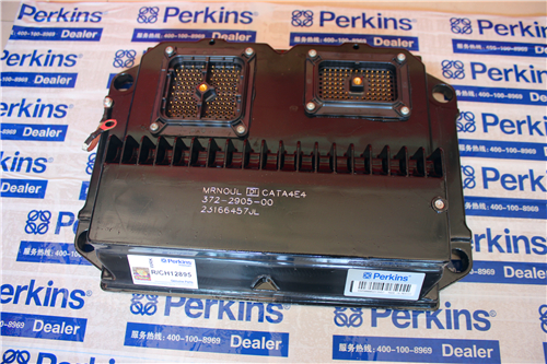
Perkins1206-E70TTA柴油發(fā)動(dòng)機(jī)引擎控制組件ECM電腦控制模塊
詳細(xì)描述
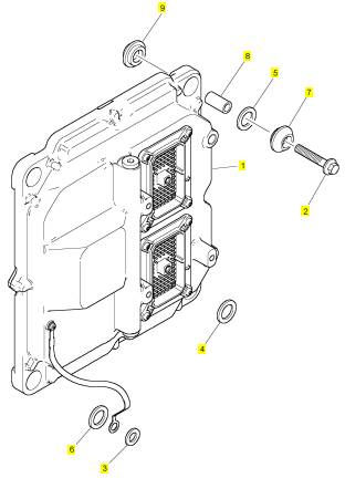
項(xiàng)目 零配件號(hào)碼 新件號(hào) 描述
1 4620006 1 4620006 引擎控制組件ECM電腦控制模塊
1 T412851 1 4620006 引擎控制組件ECM電腦控制模塊
2 2314 H008 4 2314 H008 螺旋
3 2131 A008 1 2131 A008 墊圈
4 3311 A015 1 3311 A015 墊圈
5 3311 A015 1 3311 A015 墊圈
6 3311 A015 1 3311 A015 墊圈
7 3881 A005 4 3881 A005 架設(shè)
8 3313 A027 4 3313 A027 間隔器
9 3881 A005 4 3881 A005 架設(shè)
|
KENR9101 |
|
25 |
|
Electronic Troubleshooting |
|
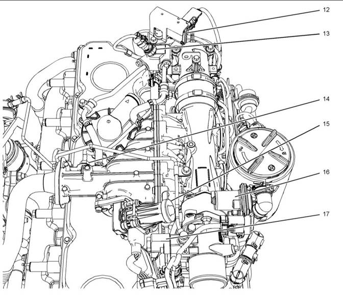
Illustration 11 |
|
g02313374 |
|
Close up views of sensor locations on the top of the engine |
|
(12) NOx Reduction System (NRS) temperaturesensor |
|
(14) NRS outlet pressure sensor (15) NRS valve with a position sensor |
|
(16) Engine intake throttle valve with a position sensor |
|
(13) NRS inlet pressure sensor |
|
(17) Wastegate regulator |
|
This document is printed from SPI². Not for RESALE |
![]()
![]()
|
26 |
|
KENR9101 |
|
Electronic Troubleshooting |
|
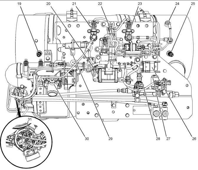
Illustration 12 |
|
g02854896 |
|
Sensors and components on a typical CEM |
|
(19) Soot antenna |
|
(23) Inlet pressure sensor for the DPF |
|
(28) ARD pilot fuel pressure sensor |
|
(20) Aftertreatment Regeneration Device (ARD) ignition coil (21) ARD air pressure sensor (22) Heater relay for the ARD nozzle |
|
(24) Inlet temperaturesensor for the DPF (25) Soot antenna (26) 40-pin harness connector (27) ARD pilot fuel control valve |
|
(29) AftertreatmentID module (30) ARD combustion air valve including a position sensor |
|
(31) Spark plug |
|
i05291450 |
|
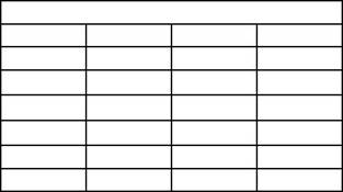
Table 5 |
|
Engine Wiring Information |
|
Color Codes for the Harness Wire |
|
Color Code |
|
Color |
|
Color Code |
|
Color |
|
BK BR |
|
Black |
|
BU |
|
Blue |
|
Harness Wire Identification |
|
Brown Red |
|
PU GY WH PK |
|
Purple Gray |
|
RD OR |
|
Perkins identifies all wires with 11 solid colors. The circuit number is stamped on the wire at a 25 mm (1 inch) spacing. Table 5 lists the wire colors and the color codes. |
|
Orange |
|
White Pink |
|
YL |
|
Yellow Green |
|
GN |
|
This document is printed from SPI². Not for RESALE |
![]()
![]()
|
KENR9101 |
|
27 |
|
Electronic Troubleshooting |
|
For example, a wire identification of X925-PK(Pink) on the schematic would signify a pink wire with the circuit number X925. X925-PK(Pink) identifies the power supply for the No. 1 injector. |
|
Note: Always replace a harness wire with the same gauge of wire and with the same color code. |
|
Note: In the following diagrams, “Px” signifies a plug and “Jx” signifies a jack. |
|
This document is printed from SPI². Not for RESALE |
![]()
|
28 |
|
KENR9101 |
|
Electronic Troubleshooting |
|
Schematic Diagrams |
|
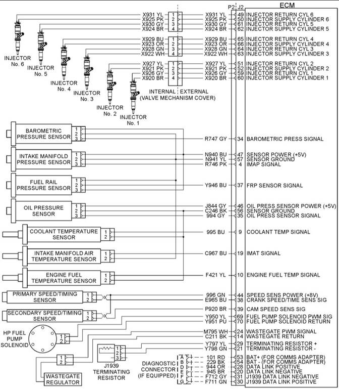
Illustration 13 |
|
g02175988 |
|
Schematic diagram of the engine connections to the J2 connector on the ECM |
|
This document is printed from SPI². Not for RESALE |
![]()
![]()
|
KENR9101 |
|
29 |
|
Electronic Troubleshooting |
|
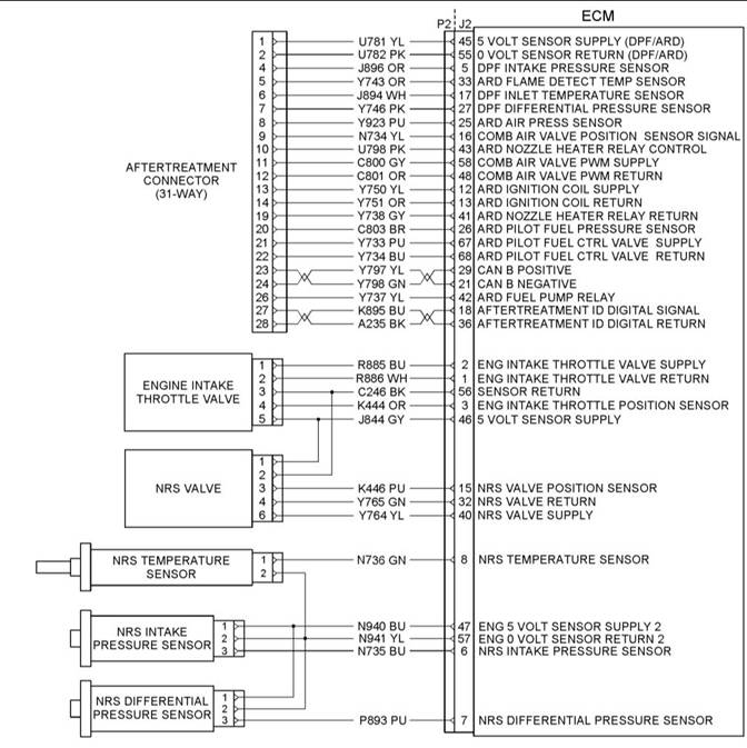
Illustration 14 |
|
g02362277 |
|
Schematic diagram of the NRS equipment |
|
This document is printed from SPI². Not for RESALE |
![]()
![]()
|
30 |
|
KENR9101 |
|
Electronic Troubleshooting |
|
Illustration 15 |
|
g02362256 |
|
Schematic diagram of the Clean Emissions Module (CEM) Sheet 1 of 2 |
|
This document is printed from SPI². Not for RESALE |