Perkins珀金斯1306-E87TA86柴油發(fā)動(dòng)機(jī)2873 K116啟動(dòng)馬達(dá)供應(yīng)商,Perkins珀金斯1306-E87TA86柴油發(fā)動(dòng)機(jī)2873 K116啟動(dòng)馬達(dá)技術(shù)價(jià)格規(guī)格咨詢服務(wù),Perkins珀金斯1306-E87TA86柴油發(fā)動(dòng)機(jī)2873 K116啟動(dòng)馬達(dá)零配件供應(yīng),Perkins珀金斯1306-E87TA86柴油發(fā)動(dòng)機(jī)2873 K116啟動(dòng)馬達(dá)售后服務(wù)中心,Perkins珀金斯1306-E87TA86柴油發(fā)動(dòng)機(jī)2873 K116啟動(dòng)馬達(dá),Perkins珀金斯1306-E87TA86柴油發(fā)動(dòng)機(jī)2873 K116啟動(dòng)馬達(dá)詳細(xì)的技術(shù)參數(shù),

首頁
產(chǎn)品展示>Perkins珀金斯1306-E87TA86柴油發(fā)動(dòng)機(jī)2873 K116啟動(dòng)馬達(dá)
產(chǎn)品中心
美國強(qiáng)鹿柴油機(jī)維修配件技術(shù)中心
約翰迪爾John Deere柴油機(jī)配件 美國麥克福斯
卡特彼勒柴油發(fā)動(dòng)機(jī)參數(shù)
沃爾沃發(fā)動(dòng)機(jī)全系參數(shù)
英國珀金斯原廠配件
珀金斯柴油機(jī)技術(shù)中心
珀金斯發(fā)動(dòng)機(jī)零件查詢圖冊(cè)
日本三菱柴油機(jī)發(fā)電機(jī)配件
德國道依茨 韓國大宇柴油發(fā)動(dòng)機(jī)配件
康明斯全系列柴油發(fā)動(dòng)機(jī)
沃爾沃 MTU 原廠配件銷售中心
瑞典沃爾沃遍達(dá)原裝柴油機(jī)配件
康明斯維修技術(shù)中心
卡特彼勒柴油發(fā)動(dòng)機(jī)原廠配件銷售中心
品牌柴油發(fā)電機(jī)組
康明斯柴油發(fā)動(dòng)機(jī)配件中心
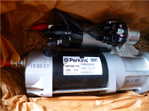
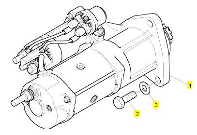
Perkins珀金斯1306-E87TA86柴油發(fā)動(dòng)機(jī)2873 K116啟動(dòng)馬達(dá)
詳細(xì)描述
項(xiàng)目 零配件號(hào)碼 新件號(hào) 描述
1 2873 K116 1 2873 K116 啟動(dòng)馬達(dá)
2 0748663 3 0748663 螺旋
3 0920444 3 0920444 墊圈
|
Peregrine EDi and 1300 Series EDi To fit |
|
Operation 5-2 |
|
Special requirements Consumable products |
|
Description |
|
Part number |
|
POWERPART Silicone RTV sealing and jointing compound |
|
1861108 |
|
Warning! Use suitable gloves to protect the hands from heat. |
|
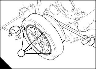
1 Heat the pulley / damper assembly. Do not exceed 198 °C (388 °F) WK, WL, WM, and WN. For WP, WQ, WR, and WS do not exceed 100 °C (212 °F). |
|
Caution: Do not try to fit a cold pulley / damper assembly as this will damage the crankshaft. |
|
2 Put the pulley assembly on the crankshaft, engage the drive key and push the pulley fully towards the rear. 3 Clean off the old sealant from the retainer plate and from the pulley / damper assembly. |
|
4 Put POWERPART Silicone RTV sealing and jointing compound on the inner face of the retainer plate and fit the retainer plate (A). |
|
5 Lubricate lightly the threads of the setscrews for the retainer plate with clean engine lubricating oil. 6 Fit and tighten the setscrews gradually and evenly to 136 Nm (100 lbf ft) 13,8 kgf m. 7 Fit the fan drive belt, see Operation 12-7. |
|
8 Fill the lubricating sump to the correct level with an approved lubricating oil, see Chapter 5 in the User’s Handbook. |
|
A |
|
W090 |
|
Workshop Manual, TPD 1353E, Issue 3 |
|
67 |
|
This document has been printed from SPI². Not for Resale |
![]()
![]()
![]()
![]()
|
5 |
|
Peregrine EDi and 1300 Series EDi |
|
To inspect |
|
Operation 5-3 |
|
Clean the components and check for damage. The assembly must be renewed if: |
|
l There are cracks in the rubber (A2) l The rubber is damaged by oil |
|
l The component alignment marks (A1) exceed the tolerance in the relevant Data and dimensions for the "Crankshaft assembly" on page 14. |
|
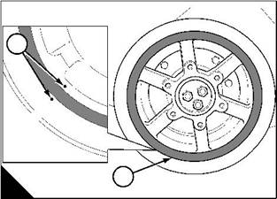
Measure and record damper alignment (B) at four places (B1) 90° apart on the damper face. Ensure that the crankshaft is at the same end of its axial movement for each measurement. This eliminates crankshaft end- float from the measurement. |
|
Before the pulley / damper assembly is removed from the crankshaft, measure and record the run-out of the damper mounting face on the crankshaft palm. |
|
Compare all the readings with the relevant Data and dimensions for the "Crankshaft assembly" on page 14. |
|
1 |
|
1 |
|
2 |
|
A |
|
B |
|
W020 |
|
W021 |
|
68 |
|
Workshop Manual, TPD 1353E, Issue 3 |
|
This document has been printed from SPI². Not for Resale |
![]()
![]()
![]()
![]()
|
5 |
|
Peregrine EDi and 1300 Series EDi |
|
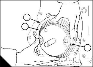
Rear oil seal housing assembly |
|
To remove the oil seal housing |
|
Operation 5-4 |
|
Cautions: |
|
l Renew the rear oil seal and the wear sleeve as a unit, do not separate them. l The flywheel housing does not have to be removed to renew the rear oil seal. 1 Drain the lubricating oil. |
|
2 Remove the lubricating oil sump, see Operation 10-9. 3 Remove the drive components from the rear end of the engine. 4 Remove the flywheel, see Operation 13-1. |
|
5 Remove the rear oil seal, see Operation 5-6. |
|
6 Remove the four setscrews that pass through the flange of the sump and into the bottom of the seal housing. 7 Remove the six setscrews that retain the seal housing to the cylinder block. |
|
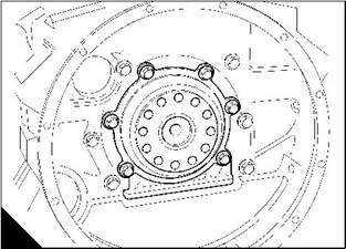
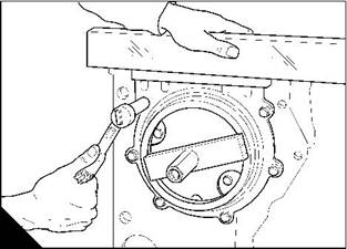
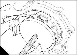
8 Remove the rear oil seal and housing assembly (A). Remove and discard the old oil seal gasket from between the housing and the cylinder block. |
|
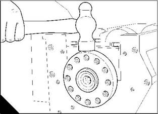
9 Hit carefully the outside diameter of the wear sleeve with a hammer to loosen the wear sleeve from the crankshaft (B). |
|
10 Remove the wear sleeve from the crankshaft. |
|
A |
|
B |
|
W045 |
|
W091 |
|
Workshop Manual, TPD 1353E, Issue 3 |
|
69 |
|
This document has been printed from SPI². Not for Resale |
![]()
![]()
![]()
![]()
![]()
|
5 |
|
Peregrine EDi and 1300 Series EDi |
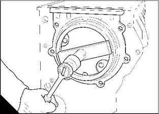
|
To fit the oil seal housing |
|
Operation 5-5 |
|
Special requirements |
|
Special tools |
|
Description |
|
Part number |
|
Rear oil seal installer |
|
21825963 |
|
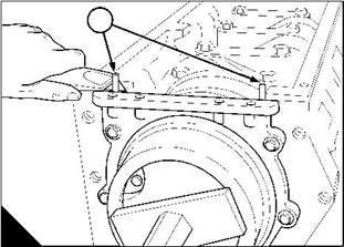
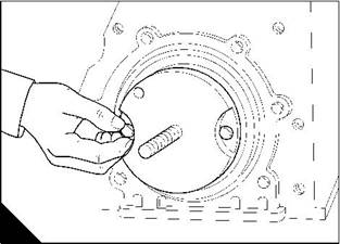
1 Clean the faces of the cylinder block, the oil seal housing and the crankshaft palm. 2 Fit the guide adaptor from tool 21825963 to the end of the crankshaft (A). 3 Fit a new seal (B1) to the oil seal housing face (B3). |
|
4 Put the housing (B2) into position on the engine, fit and tighten the setscrews finger tight. |
|
2 1 |
|
3 |
|
A |
|
B |
|
W092/1 |
|
W093 |
|
5 Fit the plate from tool 21825963 to the guide adaptor. Tighten the nut of the tool (C) until the plate comes into contact with the face of the housing. |
|
6 Use a straight edge to check that the seal housing is level with the cylinder block face (D). 7 Tighten the setscrews to 24 Nm (18 lbf ft) 2,5 kgf m. |
|
C |
|
D |
|
W048/1 |
|
W046 |
|
Continued |
|
70 |
|
Workshop Manual, TPD 1353E, Issue 3 |
|
This document has been printed from SPI². Not for Resale |
![]()
![]()
![]()
![]()


|
5 |
|
Peregrine EDi and 1300 Series EDi |
|
8 Cut off the excess seal length (E1) so that it is level with the face of the cylinder block. 9 Remove the tool 21825963. |
|
10 Fit the new rear oil seal / wear sleeve and the POSE seal, see Operation 5-6. 11 Fit the lubricating oil sump, see Operation 10-10. |
|
12 Fit the flywheel, see Operation 13-2. |
|
13 Fit the drive components to the rear end of the engine. |
|
14 Fill the lubricating oil sump to the correct level with an approved lubricating oil, see Chapter 5 in the User’s Handbook. |
|
1 |
|
E |
|
W047 |
|
Workshop Manual, TPD 1353E, Issue 3 |
|
71 |
|
This document has been printed from SPI². Not for Resale |
![]()
![]()
|
5 |
|
Peregrine EDi and 1300 Series EDi |
|
To renew the rear oil seal and wear sleeve assembly |
|
Operation 5-6 |
|
Special requirements Special tools |
|
Consumable products |
|
Description |
|
Part number ZTSE 4404 21825963 |
|
Description |
|
Part number |
|
Remover for the wear sleeve of the rear oil seal |
|
POWERPART Compound |
|
1861147 |
|
Rear oil seal installer |
|
Notes: |
|
l The oil seal housing does not have to be removed to renew the rear oil seal and wear sleeve assembly. l The flywheel housing does not have to be removed to renew the rear oil seal and wear sleeve assembly. l Renew the rear oil seal and the wear sleeve as a unit, do not separate them. 1 Drain the lubricating oil. |
|
2 Remove the drive components from the rear end of the engine. 3 Remove the flywheel, see Operation 13-1. |
|
Note: From engine number N1194039, types WP, WQ, WR and WS, a new rear oil seal assembly has been introduced that prevents the entry of debris from the environment. The seal includes a ‘Positive On-Shaft Excluder’ (P.O.S.E.), which extends the life of the seal. |
|
4 Use a suitable smooth tool to remove the POSE seal from the rear oil seal wear sleeve (A). 5 Fit two self-tapping screws (B2) into the front face (B1) of the oil seal. 6 Carefully lever the seal from the seal housing (B). |
|
Caution: Do not damage the seal housing or the crankshaft palm. |
|
1 |
|
2 |
|
A |
|
B |
|
W1386 |
|
W094 |
|
Continued |
|
72 |
|
Workshop Manual, TPD 1353E, Issue 3 |
|
This document has been printed from SPI². Not for Resale |
![]()
![]()
![]()
![]()
![]()

|
5 |
|
Peregrine EDi and 1300 Series EDi |
|
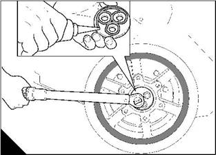
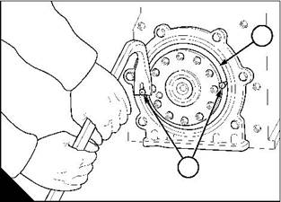
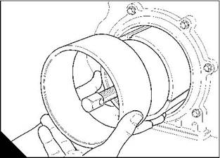
7 Fit the remover tool ZTSE 4404 (C) and (D). |
|
C |
|
D |
|
W226 |
|
W227 |
|
8 Fit a square headed lever (E1) into the 12,7 mm (0.5 in) hole in the front face of the remover tool (E3). |
|
9 Fit a spanner (E4) to the threaded rod (E2) of the remover tool. Hold the lever and tighten the threaded rod with the spanner to remove the wear sleeve. |
|
10 Discard the oil seal and wear sleeve. |
|
11 Clean the oil seal housing and the crankshaft palm. 12 Fit the guide adaptor (F) from tool 21825963 to the end of the crankshaft. |
|
13 Apply POWERPART Compound to the outer diameter of the oil seal and to the inner diameter of the wear sleeve. |
|
Caution: Fit the rear oil seal and the wear sleeve as a unit, do not separate them. |
|
3 |
|
2 |
|
1 |
|
4 |
|
E |
|
F |
|
W228 |
|
W092/1 |
|
Continued |
|
Workshop Manual, TPD 1353E, Issue 3 |
|
73 |
|
This document has been printed from SPI². Not for Resale |
![]()
![]()
|
5 |
|
Peregrine EDi and 1300 Series EDi |
|
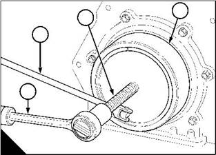
14 Put the oil seal and wear sleeve assembly (G1) into position on the guide adaptor (G3) from tool 21825963. |
|
15 Fit the plate from tool 21825963 to the guide adaptor. Tighten the nut of the tool until the plate comes into contact with the face of the housing (H). |
|
2 1 |
|
3 |
|
G |
|
H |
|
W093 |
|
W048 |
|
Note: When the plate from tool 21825963 comes into contact with the face of the seal housing, the oil seal and the wear sleeve are in their correct positions. |
|
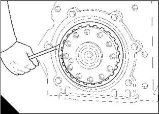
16 Fit the new POS, E seal (J1) to the wear sleeve on the crankshaft palm by hand until it is fully in position. 17 Fit the flywheel, see Operation 13-2. |
|
18 Fit the drive components to the rear end of the engine. |
|
19 Fill the lubricating oil sump to the correct level with an approved lubricating oil, see Chapter 5 in the User’s Handbook. |
|
1 |
|
J |
|
W1385 |
|
74 |
|
Workshop Manual, TPD 1353E, Issue 3 |
|
This document has been printed from SPI². Not for Resale |
![]()
![]()
|
5 |
|
Peregrine EDi and 1300 Series EDi |
|
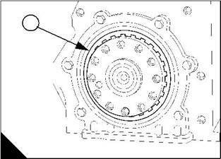
Crankshaft |
|
To remove |
|
Operation 5-7 |
|
Warning! Use lift equipment or obtain assistance to lift heavy engine components such as the flywheel housing, flywheel and crankshaft. |
|
1 Drain the lubricating oil and the coolant. |
|
2 Remove the lubricating oil sump, see Operation 10-9. 3 Remove the fan drive belt, see Operation 12-7. |
|
4 Remove the fan, see Operation 12-5. |
|
5 Remove the fan drive pulley and fan mounting, see Operation 12-6. 6 Remove the coolant pump, see Operation 12-4. |
|
7 Remove the pulley / damper assembly, see Operation 5-1. 8 Remove the alternator and its mounting bracket, see Operation 14-1. 9 Remove the compressor and its drive assembly, if one is fitted, see Operation 15-1. 10 Remove the timing case cover, see Operation 6-1. 11 Remove the high-pressure pump, see Operation 10-21. 12 Remove the timing case backplate, see Operation 6-5. 13 Remove the flywheel, see Operation 13-1. |
|
14 Remove the flywheel housing, see Operation 13-4. 15 Remove the rear oil seal housing assembly, see Operation 5-4. 16 Remove the lubricating oil suction pipe and strainer, see Operation 10-11. 17 Remove the lubricating oil pump, see Operation 10-12. |
|
18 Remove the big end bearing caps (A) from the connecting rods. Keep the shell-bearings and their shell- bearing caps together. |
|
190 |
|
4 |
|
5 |
|
190 |
|
A |
|
W082/1 |
|
Continued |
|
Workshop Manual, TPD 1353E, Issue 3 |
|
75 |
|
This document has been printed from SPI². Not for Resale |