Perkins珀金斯900 3.152柴油發(fā)動(dòng)機(jī)3142 A081排氣閥/ZZ80235汽缸蓋總成供應(yīng)商,Perkins珀金斯900 3.152柴油發(fā)動(dòng)機(jī)3142 A081排氣閥/ZZ80235汽缸蓋總成技術(shù)價(jià)格規(guī)格咨詢服務(wù),Perkins珀金斯900 3.152柴油發(fā)動(dòng)機(jī)3142 A081排氣閥/ZZ80235汽缸蓋總成零配件供應(yīng),Perkins珀金斯900 3.152柴油發(fā)動(dòng)機(jī)3142 A081排氣閥/ZZ80235汽缸蓋總成售后服務(wù)中心,Perkins珀金斯900 3.152柴油發(fā)動(dòng)機(jī)3142 A081排氣閥/ZZ80235汽缸蓋總成,Perkins珀金斯900 3.152柴油發(fā)動(dòng)機(jī)3142 A081排氣閥/ZZ80235汽缸蓋總成詳細(xì)的技術(shù)參數(shù),

首頁(yè)
產(chǎn)品展示>Perkins珀金斯900 3.152柴油發(fā)動(dòng)機(jī)3142 A081排氣閥/ZZ80235汽缸蓋總成
產(chǎn)品中心
美國(guó)強(qiáng)鹿柴油機(jī)維修配件技術(shù)中心
約翰迪爾John Deere柴油機(jī)配件 美國(guó)麥克福斯
卡特彼勒柴油發(fā)動(dòng)機(jī)參數(shù)
沃爾沃發(fā)動(dòng)機(jī)全系參數(shù)
英國(guó)珀金斯原廠配件
珀金斯柴油機(jī)技術(shù)中心
珀金斯發(fā)動(dòng)機(jī)零件查詢圖冊(cè)
日本三菱柴油機(jī)發(fā)電機(jī)配件
德國(guó)道依茨 韓國(guó)大宇柴油發(fā)動(dòng)機(jī)配件
康明斯全系列柴油發(fā)動(dòng)機(jī)
沃爾沃 MTU 原廠配件銷售中心
瑞典沃爾沃遍達(dá)原裝柴油機(jī)配件
康明斯維修技術(shù)中心
卡特彼勒柴油發(fā)動(dòng)機(jī)原廠配件銷售中心
品牌柴油發(fā)電機(jī)組
康明斯柴油發(fā)動(dòng)機(jī)配件中心
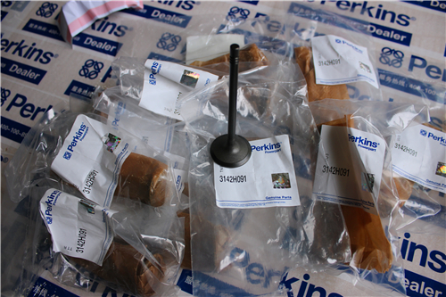
Perkins珀金斯900 3.152柴油發(fā)動(dòng)機(jī)3142 A081排氣閥/ZZ80235汽缸蓋總成
詳細(xì)描述
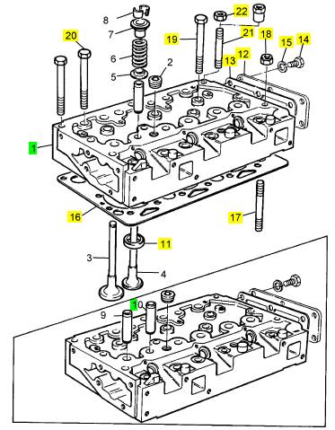
項(xiàng)目 零配件號(hào)碼 最新件號(hào) 描述
3142 A081 3 3142 A081 排氣閥
1 ZZ80235 1 ZZ80235 汽缸蓋總成
(1) ZZ80235P 1 ZZ80235R 汽缸蓋總成 -EXCH
11 33124428 3 33124428 閥座氣門座圈
12 1 蓋
13 1 接合
14 6 螺旋
15 6 墊圈
16 3681 E024 1 3681 E024 汽缸蓋墊片
17 32524132 1 32524132 圖釘
18 33221329 1 33221329 螺帽
19 32181457 5 32181457 汽缸蓋螺拴
20 32181458 9 32181458 汽缸蓋螺拴
21 32524148 3 32524148 圖釘
22 33221329 3 33221329 螺帽
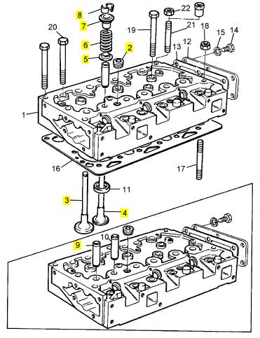
項(xiàng)目 零配件號(hào)碼 最新件號(hào) 描述
ZZ80017 1 檢查歷史 汽缸蓋總成
2 2431154 2 2431154 栓塞
2 2431154 2 2431154 栓塞
3 31431681 3 31431681 進(jìn)氣閥
4 31431031 3 31431031 排氣閥
5 33415133 6 33415133 彈簧塾圈
6 0780012 6 0780012 閥彈簧
7 33423148 6 33423148 帽
8 0230001 12 0230001 閥筒夾
8 0230001 6 0230001 閥筒夾
9 U3316A031 3 3316 A031 氣門導(dǎo)管
10 U3313E734 3 3313 E734 氣門導(dǎo)管
|
Disassembly and Assembly Section |
|
g01383260 |
|
g01383261 |
|
Illustration 42 |
|
Illustration 44 |
|
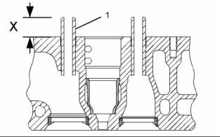
1. Use Tooling (A) and a hammer in order to remove the valve guides from the cylinder head. |
|
2. Use Tooling (A) and Tooling (B) to install valve guides (1) in the cylinder head. |
|
Installation Procedure |
|
Note: Tooling (B) must be used in order to install the valve guides to the correct height. |
|
Table 13 |
|
Height (X) from the top of the valve guide to the cylinder head surface ................ 35.00 ± 0.50 mm (1.378 ± 0.020 inch) |
|
Required Tools |
|
Tool A |
|
Part Number CVT0001 |
|
Part Description Valve Guide Driver Valve Guide Collar |
|
Qty 1 |
|
For more information, refer to Specifications, “Cylinder Head Valves”. |
|
B |
|
CVT0002 |
|
1 |
|
End By: |
|
NOTICE |
|
Keep all parts clean from contaminants. |
|
a. Install the inlet and exhaust valves. Refer to Disassembly and Assembly, “Inlet and Exhaust Valves - Remove and Install”. |
|
Contaminants may cause rapid wear and shortened component life. |
|
i02754779 Engine Oil Filter Base - Remove |
|
1. Lubricate the parent bores for the valve guides in the cylinder head with clean engine oil. |
|
Removal Procedure |
|
NOTICE Keep all parts clean from contaminants. |
|
Contaminants may cause rapid wear and shortened component life. |
|
g01383265 |
|
Illustration 43 |
|
This document has been printed from SPI². Not for Resale |
![]()
![]()

![]()
![]()
![]()

![]()
![]()
![]()
|
KENR6906 |
|
25 Disassembly and Assembly Section |
|
NOTICE |
|
Care must be taken to ensure that fluids are contained during performance of inspection, maintenance, test- ing, adjusting and repair of the product. Be prepared to collect the fluid with suitable containers before open- ing any compartment or disassembling any compo- nent containing fluids. |
|
Dispose of all fluids according to local regulations and mandates. |
|
1. Place a suitable container below the engine oil filter base in order to drain the engine oil. |
|
g01401581 |
|
Illustration 46 |
|
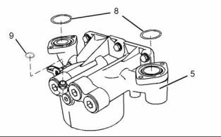
9. Remove O-ring seals (8) and O-ring seal (9) from engine oil filter base (5). |
|
g01404137 |
|
Illustration 47 |
|
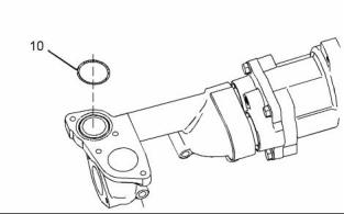
10. Remove O-ring seal (10) from the engine oil pump. |
|
g01396094 |
|
Illustration 45 |
|
2. Remove plug (8). Allow the engine oil to drain. |
|
i02754781 Engine Oil Filter Base - Disassemble |
|
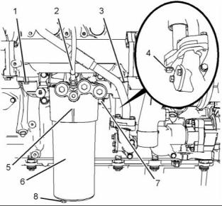
3. Remove engine oil filter (6) from engine oil filter base (5). Remove the O-ring seal and remove the filter element from the engine oil filter. Refer to Operation and Maintenance Manual, “Engine Oil and Filter - Change” for more information. |
|
4. Disconnect hose assembly (2) from engine oil filter base (5). |
|
Disassembly Procedure |
|
5. Remove bolts (1) and (3). |
|
Start By: |
|
6. Remove bolts (4) in order to disconnect the tube assembly from the engine oil pump. |
|
a. Remove the engine oil filter base. Refer to Disassembly and Assembly, “Engine Oil Filter Base - Remove”. |
|
7. Support the weight of the engine oil cooler. The engine oil cooler weighs approximately 23 kg (50 lb). |
|
NOTICE Keep all parts clean from contaminants. |
|
8. Remove engine oil filter base (5) and remove the joint. |
|
Contaminants may cause rapid wear and shortened component life. |
|
This document has been printed from SPI². Not for Resale |
![]()
![]()
![]()
![]()
![]()
![]()
![]()
![]()
|
26 |
|
KENR6906 |
|
Disassembly and Assembly Section |
|
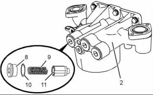
b. Remove spring (9). |
|
c. Remove plunger (11). |
|
Personal injury can result from being struck by parts propelled by a released spring force. |
|
Make sure to wear all necessary protective equip- ment. |
|
Follow the recommended procedure and use all recommended tooling to release the spring force. |
|
g01396108 |
|
Illustration 50 |
|
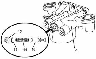
4. Follow Steps 4.a through 4.c in order to remove the oil cooler bypass valve. |
|
a. Remove plug (12) from engine oil filter base (2). Remove O-ring seal (13) from plug (12). |
|
g01380571 |
|
Illustration 48 |
|
b. Remove spring assembly (14). c. Remove plunger (15). |
|
1. If necessary, remove oil sampling valve (1) from engine oil filter base (2). Remove the O-ring seal from the oil sampling valve. |
|
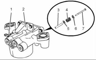
2. Follow Steps 2.a and 2.b in order to remove the high pressure relief valve. |
|
a. Remove bolt (7) from engine oil filter base (2). |
|
b. Remove cap (6), spring (4), seat (5) and sleeve (3) from engine oil filter base (2). |
|
g01396110 |
|
Illustration 51 |
|
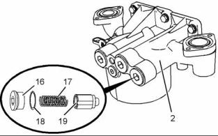
5. Follow Steps 5.a through 5.c in order to remove the oil pump bypass valve. |
|
a. Remove plug (16) from engine oil filter base (2). Remove O-ring seal (18) from plug (16). |
|
b. Remove spring (17). c. Remove plunger (19). |
|
g01396109 |
|
Illustration 49 |
|
3. Follow Steps 3.a through 3.c in order to remove the oil filter bypass valve. |
|
a. Remove plug (8) from engine oil filter base (2). Remove O-ring seal (10) from plug (8). |
|
This document has been printed from SPI². Not for Resale |
![]()
![]()
![]()
![]()
![]()
![]()
![]()
|
KENR6906 |
|
27 Disassembly and Assembly Section |
|
i02754782 |
|
Engine Oil Filter Base - Assemble |
|
Assembly Procedure |
|
NOTICE Keep all parts clean from contaminants. |
|
Contaminants may cause rapid wear and shortened component life. |
|
g01396108 |
|
Illustration 53 |
|
3. Follow Steps 3.a through 3.d in order to install the oil cooler bypass valve. |
|
Improper assembly of parts that are spring loaded can cause bodily injury. |
|
a. Lubricate spring assembly (14), and plunger (15) with clean engine oil. |
|
To prevent possible injury, follow the established assembly procedure and wear protective equip- ment. |
|
b. Install spring assembly (14), and plunger (15) into engine oil filter base (2). |
|
c. Install a new O-ring seal (13) to plug (12). |
|
1. Inspect the components for wear or damage. Replace any components that are worn or damaged. |
|
d. Install plug (12) to engine oil filter base (2). Tighten the plug to a torque of 100 N·m (74 lb ft). |
|
g01396110 |
|
Illustration 52 |
|
g01396109 |
|
Illustration 54 |
|
2. Follow Steps 2.a through 2.d in order to install the oil pump bypass valve. |
|
4. Follow Steps 4.a through 4.d in order to install the oil filter bypass valve. |
|
a. Lubricate plunger (19) and spring (17) with clean engine oil. |
|
a. Lubricate plunger (11) and spring (9) with clean engine oil. |
|
b. Install plunger (19) and spring (17) into engine oil filter base (2). |
|
b. Install plunger (11) and spring (9) into engine oil filter base (2). |
|
c. Install a new O-ring seal (18) to plug (16). |
|
c. Install a new O-ring seal (10) to plug (8). |
|
d. Install plug (16) to engine oil filter base (2). Tighten the plug to a torque of 100 N·m (74 lb ft). |
|
d. Install plug (8) to engine oil filter base (2). Tighten the plug to a torque of 100 N·m (74 lb ft). |
|
This document has been printed from SPI². Not for Resale |